Determine the stripe size
The default stripe size for the Silicon Image RAID controller SiL3112 is 16KB (32 sectors) when a RAID 0 array is created in ‘Automatic’ mode. However if the stripe size is guessed incorrectly and the array is recreated, the data will not be contiguous and therefore appear corrupt and inaccessible – writing to the disk will then cause real corruption to the data.
One way to determine the stripe size is to compare the first 100 or so sectors of each disk to a single non-RAID disk with, for example, the sample operating system installed. This will be illustrated with NTFS and Windows XP:
Note: Physical Sector refers to the contiguous sectors on one physical disk. Logical Sector refers to a sector in the RAID 0 array, i.e. contained in the logical RAID disk. Data bytes are written in hexadecimal. An empty sector contains all zeros. I have not read the NTFS specification, so most of the following information I have inferred.
Examining a healthy single-NTFS-partition installation of Windows XP on an individual disk reveals the following information (in physical sectors):
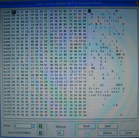
1) The MBR in sector 0 contains one entry describing the extents of the single NTFS partition.
The raw data looks like this:
This sector has the signature:
EB 52 90 4E 54 46 53
Ù R É N T F S
which can be seen in the following image:
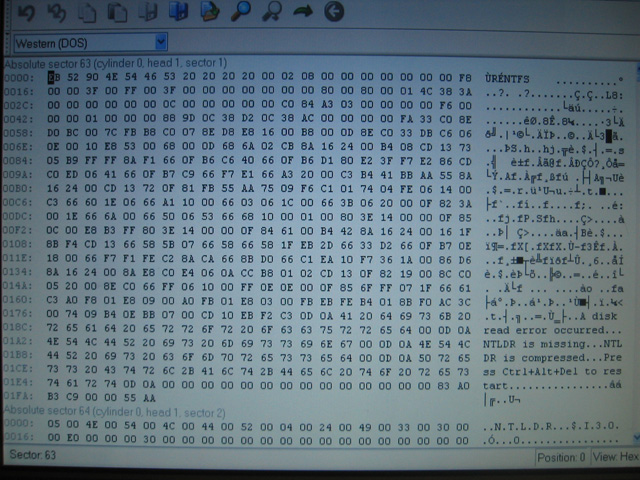
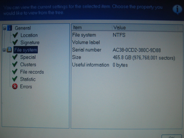
This can be made human-readable using the appropriate sector viewing program:
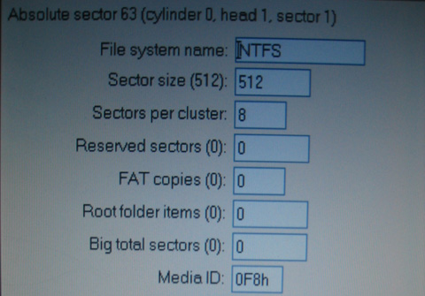
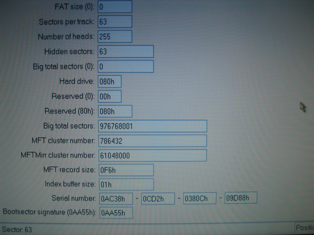
The standard number of ‘hidden sectors’ is 63, so tells NTFS to ignore the first 63 sectors (0-62) on the disk. The total number of ‘big’ NTFS sectors should be equal to the actual number of sectors described in the MBR for this partition minus 2. That is:
((#EndSector - #StartSector + 1) - 2)
The ‘Size’ value in the following image is the same as ‘Big total sectors’ above:
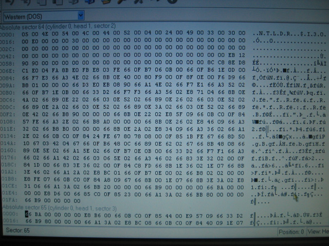
4) The next 6 sectors (64-69) contain the NTLDR boot code, and appear as ‘dense’ hex information when viewed raw.
The first bytes of this sector are:
N T L D R
which contains the Unicode string ‘NTLDR’ from 4E onward, shown here:
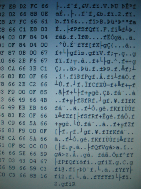
A ‘dense’ sector looks like the following, which is actually another sector of NTLDR:
5) The next 9 sectors (70-78) are empty.
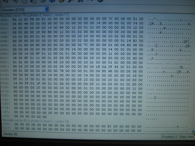
6) The following sectors appear ‘sparse’ in a raw hex view and probably contain directory information.
F0 12 03 F8 00
(this should be the same across all NTFS partitions, but it is not know to be fact)
Sector 80 begins with:
FE 2C 93 CA
(this should be the same across all NTFS partitions, but it is not know to be fact)
A ‘sparse’ sector has many zeros in it, such as in the following image, which is a sector taken from a nearby sector:
Eventually the partial Unicode names of directories with appear (eg: “$???Install”), such as the service pack/patch uninstall directories that reside in the main Windows directory.
7) Both the NTFS partition information and NTLDR boot code are repeated many times on the disk. However they do not begin at the start of a cluster – they are offset by an arbitrary number of bytes. Therefore doing a straight sector-to-sector copy of this data will not work!
This was enough information to help determine what the stripe size was in the original RAID 0 array. Since the sector size is half-a-kilobyte, to calculate the number of sectors in a certain-sized stripe, just multiply the stripe size by 2. For example, a 16KB stripe contains 32 sectors.
It is important to note that it is impossible to determine stripe ordering from portions of the disc that one has no semantic information about because an LS will always reside on the same drive in an array for stripe sizes smaller than its PS offset (since it is a multiple of the index of the drive in the array). For example, LS 63 would always be in PS 31 of the same physical disk if the stripe size was 16kB, 8kB, 4kB or 2kB. But if the size was 32kB (meaning one stripe contained 64 clusters) then LS 63 would definitely be on the first physical disk of the array. What is of interest to us is how the LSs are striped (grouped) and how these stripes are connected in order to form the original contiguous data on the logical disk.
The recovery process that inspired this guide dealt with two 250GB physical disks (say disk A and B, no order implied) in a RAID 0 array containing one NTFS partition with Windows XP, with a 16kB stripe size or 32 clusters per stripe (although this last fact was not know in the beginning).
The stripe size was inferred by using the knowledge of what is contained in the first 100-or-so sectors of the single-physical-disk install of Windows XP on NTFS described above.
Disk A revealed the following:
- A mostly-sane looking MBR was found with one entry. The partition information was partially corrupted.
- The NTLDR boot code was found at PS 32, before which there was empty space.
- Immediately after this, there were 9 sectors of empty space and then what appeared to be a portion of the sparse file table, the first sector of which began with the same data as in the case of the single disk.
-
An MBR containing four entries, each of which described junk (eg: a few partitions extending into the terabytes).
-
PS 31 contained the NTFS partition information, before which there was empty space.
-
Immediately following (from PS 32 onwards) appeared data also resembling the sparse file table.
Since we know that NTLDR immediately follows the NTFS partition information, we can safely rule out stripe sizes above 16kB (since they would then reside on the same disk).
We can now narrow down the stripe size possibilities by examining the sectors following NTLDR on disk A and NTFS info on disk B. Since we know on a non-RAID single-disk install, the NTLDR boot code continues for 6 sectors, followed by 9 sectors of empty space, and then the beginning of the sparse file table of which we know the first few bytes of data, we simply have to see how these sectors are split across the two disks.
In this case all of these sectors are contained on the same physical disk, which leaves us with the possible stripe sizes of 8kB (16 clusters) or 16kB (32 clusters). Further examination of the sparse file table (cross-checking the first bytes of subsequent sectors with what one would expect on a single-disk install) showed that the data continued for more that 16 clusters, which eliminated that option and left the final stripe size of 16kB.
Since we now know the mapping of PS between the disks to LS of the RAID array, we can see that disk A is #1 in the array, and disk B is #2 in the array.
Popular content
Today's:
- About
- Turning the Navman S150 into a Bluetooth GPS receiver
- Update
- My blog lives elsewhere...
- Simplified Makefile System
- Making your iPhone look like a NMEA GPS receiver with gpsd and WiFi or Bluetooth
- Restore the MBR and partition information, therefore restoring the file system
- Australian Geographical RadioFrequency Map
- NISRP: the Non-Intrusive Song Rating Plugin for Winamp and iTunes
- How to recover a RAID 0 disk array after losing the array’s metadata
All time:
- About
- How to recover a RAID 0 disk array after losing the array’s metadata
- Making your iPhone look like a NMEA GPS receiver with gpsd and WiFi or Bluetooth
- Aircraft Tracking with Mode S: Modez & Aviation Mapper
- Australian Geographical RadioFrequency Map
- Windows Side-by-Side Assemblies (WinSxS)
- Dual monitor Quake III
- Determine the order of the physical disks in the array
- Tearable Cloth
- Software Defined Radio
Last viewed:
- Update
- Windows Side-by-Side Assemblies (WinSxS)
- About
- My blog lives elsewhere...
- Turning the Navman S150 into a Bluetooth GPS receiver
- Update
- Simplified Makefile System
- Australian Geographical RadioFrequency Map
- Restore the MBR and partition information, therefore restoring the file system
- WiFi Antennas
AntiSpam spam counter

Comments
How to view MBR
How are you getting these screens? What utilities are used for each step?
RE: How to view MBR
Check out the last page of this guide for the list.
Re: raid & stripe size
Very good description how a raid worksand what problemes can appear. I have learned a lot by reading - thank you for that!