How to recover a RAID 0 disk array after losing the array’s metadata
(unfortunately this will not help if you lose an entire disk*)
The vast majority of the information presented here I inferred from my own recovery experience – it may be inaccurate or utterly wrong, so use it at your own risk. I do not take any responsibility whatsoever for your data after you apply any of the knowledge described in this document.
RAID 0 (AKA ‘striping’) creates one logical disk out of multiple, identical physical disks. The total capacity is the sum of the individual disks. It offers higher data throughput, but does not actually provide any data redundancy whatsoever. Each disk is proportioned into many identically-sized ‘stripes’, which form a continuous chain when seen from the point of view of the whole logical disk. The stripes are shared in such a way that the first physical disk contains the first stripe, the second physical disk the second, and so on, until we return to the first physical disk where the count continues. The RAID controller stores metadata in track 0 of the physical disk(s) that dictates the configuration of the RAID array. If this metadata is corrupted or lost, the logical RAID 0 disk will be lost, the controller will treat the physical drives as individual, separate logical drives and the data will be inaccessible because it is split over multiple discs. This guide attempts to show how one can recover the logical RAID 0 disk when little information is know about physical & logical disk parameters, and partition & file system information a priori.
Introduction
The reader should be familiar with such terms as:
· Sector (smallest addressable block of data on a disk, usually 512 bytes)
· Master Boot Record (a table in sector 0 containing four entries that describes how areas of data is laid out on the disk)
· Track 0 (consists of all the sectors in cylinder 0, head 0 of the disk, which contains the MBR and metadata, usually sectors 0-63)
· File system Cluster (a cluster contains a fixed number of sectors, eg: 8, which yields 4KB clusters)
· Partition information block (commonly a single sector that contains information about the file system in a partition, eg: the cluster size, cluster count, position of metadata, etc)
Symptoms of system with corrupt RAID 0 disk arrays are:
· Each individual physical disk appears as an unformatted/uninitialised disk.
· If the array was bootable, receiving one of the following messages following POST when the BIOS is attempting to find media with an operating system:
o “MBR Error”
o “Invalid partition table”
o “Press any key to boot from floppy”
o “A disk error occurred”
o “Invalid operating system”
Recommended Reading Material
Overview
To recover a RAID 0 array (and therefore the lost data), the following steps must be taken:
1) Determine the order of the physical disks in the array
2) Determine the stripe size
3) Back up relevant data in track 0 from all drives (such as the MBR, partition information, etc)
4) Re-create the RAID 0 array with the correct settings
5) Restore the MBR and partition information, therefore restoring the file system
Determine the order of the physical disks in the array
The first disk can be identified by an MBR that contains an entry resembling the original extent of the logical RAID disk. For example, if two identically-sized disks were used, then the end-sector of the MBR entry would be approximately twice the number of total sectors on a single disk. The other disks would contain MBRs with odd entries and can be ignored. If it is unclear or all values are nonsensical, the next step will help.
Here is an example of the human-readable values in the MBR from the recovered RAID array:
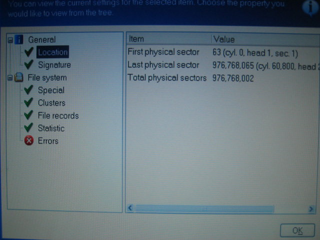
This calculation doesn’t make sense to me: isn’t #Total = (#Last - #First + 1)? Therefore I assume it should be 976768003 total physical sectors. Regardless, one must use the numbers seen in the NTFS partition information sector described later.
Determine the stripe size
The default stripe size for the Silicon Image RAID controller SiL3112 is 16KB (32 sectors) when a RAID 0 array is created in ‘Automatic’ mode. However if the stripe size is guessed incorrectly and the array is recreated, the data will not be contiguous and therefore appear corrupt and inaccessible – writing to the disk will then cause real corruption to the data.
One way to determine the stripe size is to compare the first 100 or so sectors of each disk to a single non-RAID disk with, for example, the sample operating system installed. This will be illustrated with NTFS and Windows XP:
Note: Physical Sector refers to the contiguous sectors on one physical disk. Logical Sector refers to a sector in the RAID 0 array, i.e. contained in the logical RAID disk. Data bytes are written in hexadecimal. An empty sector contains all zeros. I have not read the NTFS specification, so most of the following information I have inferred.
Examining a healthy single-NTFS-partition installation of Windows XP on an individual disk reveals the following information (in physical sectors):
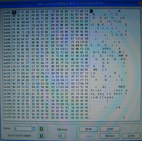
1) The MBR in sector 0 contains one entry describing the extents of the single NTFS partition.
The raw data looks like this:
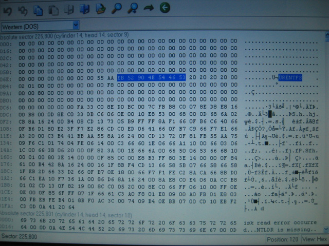
This sector has the signature:
EB 52 90 4E 54 46 53
Ù R É N T F S
which can be seen in the following image:
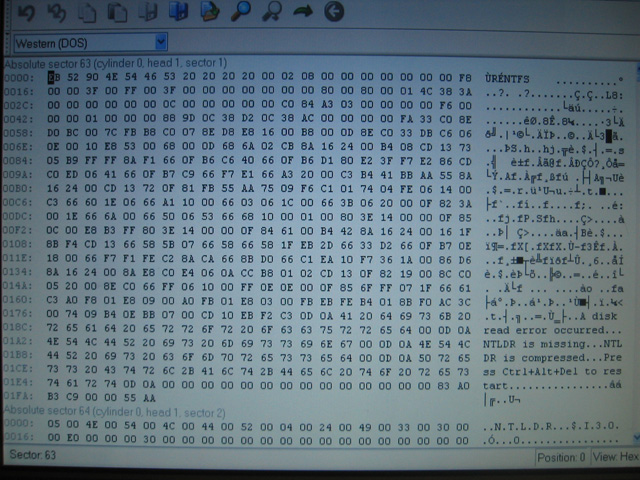
This can be made human-readable using the appropriate sector viewing program:
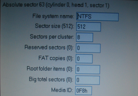
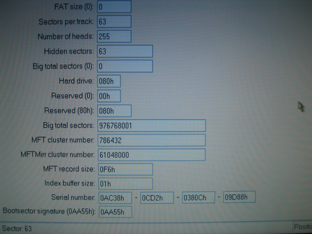
The standard number of ‘hidden sectors’ is 63, so tells NTFS to ignore the first 63 sectors (0-62) on the disk. The total number of ‘big’ NTFS sectors should be equal to the actual number of sectors described in the MBR for this partition minus 2. That is:
((#EndSector - #StartSector + 1) - 2)
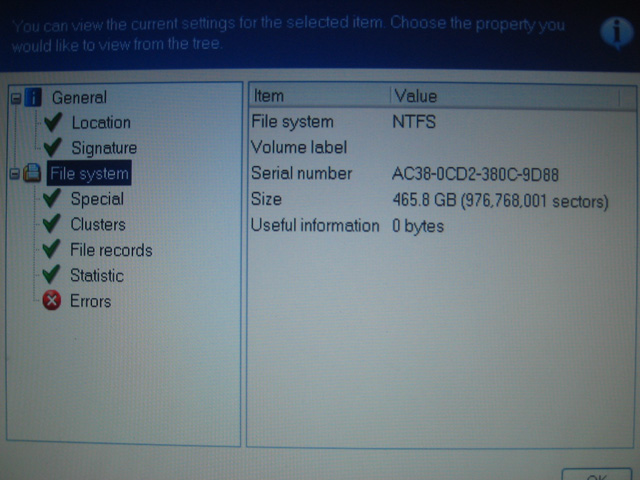
The ‘Size’ value in the following image is the same as ‘Big total sectors’ above:
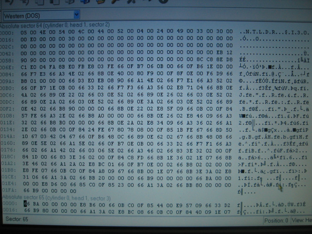
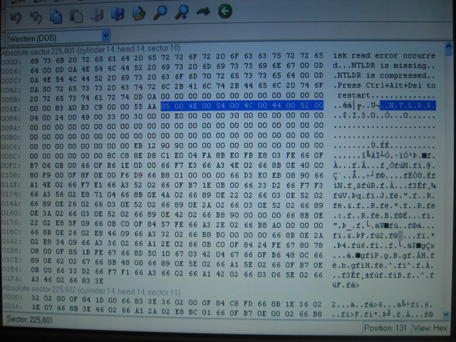
4) The next 6 sectors (64-69) contain the NTLDR boot code, and appear as ‘dense’ hex information when viewed raw.
The first bytes of this sector are:
N T L D R
which contains the Unicode string ‘NTLDR’ from 4E onward, shown here:
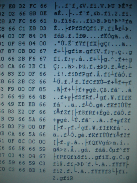
A ‘dense’ sector looks like the following, which is actually another sector of NTLDR:
5) The next 9 sectors (70-78) are empty.
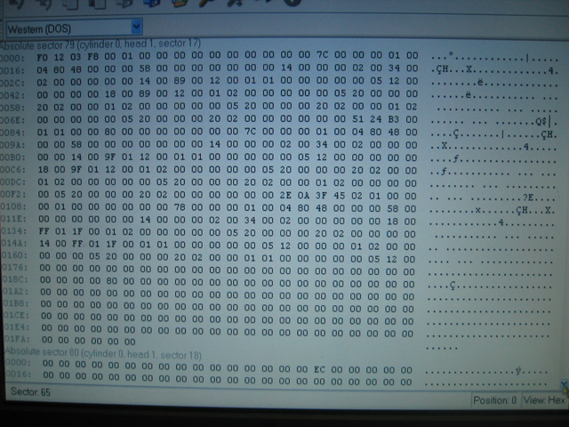
6) The following sectors appear ‘sparse’ in a raw hex view and probably contain directory information.
F0 12 03 F8 00
(this should be the same across all NTFS partitions, but it is not know to be fact)
Sector 80 begins with:
FE 2C 93 CA
(this should be the same across all NTFS partitions, but it is not know to be fact)
A ‘sparse’ sector has many zeros in it, such as in the following image, which is a sector taken from a nearby sector:
Eventually the partial Unicode names of directories with appear (eg: “$???Install”), such as the service pack/patch uninstall directories that reside in the main Windows directory.
7) Both the NTFS partition information and NTLDR boot code are repeated many times on the disk. However they do not begin at the start of a cluster – they are offset by an arbitrary number of bytes. Therefore doing a straight sector-to-sector copy of this data will not work!
This was enough information to help determine what the stripe size was in the original RAID 0 array. Since the sector size is half-a-kilobyte, to calculate the number of sectors in a certain-sized stripe, just multiply the stripe size by 2. For example, a 16KB stripe contains 32 sectors.
It is important to note that it is impossible to determine stripe ordering from portions of the disc that one has no semantic information about because an LS will always reside on the same drive in an array for stripe sizes smaller than its PS offset (since it is a multiple of the index of the drive in the array). For example, LS 63 would always be in PS 31 of the same physical disk if the stripe size was 16kB, 8kB, 4kB or 2kB. But if the size was 32kB (meaning one stripe contained 64 clusters) then LS 63 would definitely be on the first physical disk of the array. What is of interest to us is how the LSs are striped (grouped) and how these stripes are connected in order to form the original contiguous data on the logical disk.
The recovery process that inspired this guide dealt with two 250GB physical disks (say disk A and B, no order implied) in a RAID 0 array containing one NTFS partition with Windows XP, with a 16kB stripe size or 32 clusters per stripe (although this last fact was not know in the beginning).
The stripe size was inferred by using the knowledge of what is contained in the first 100-or-so sectors of the single-physical-disk install of Windows XP on NTFS described above.
Disk A revealed the following:
- A mostly-sane looking MBR was found with one entry. The partition information was partially corrupted.
- The NTLDR boot code was found at PS 32, before which there was empty space.
- Immediately after this, there were 9 sectors of empty space and then what appeared to be a portion of the sparse file table, the first sector of which began with the same data as in the case of the single disk.
-
An MBR containing four entries, each of which described junk (eg: a few partitions extending into the terabytes).
-
PS 31 contained the NTFS partition information, before which there was empty space.
-
Immediately following (from PS 32 onwards) appeared data also resembling the sparse file table.
Since we know that NTLDR immediately follows the NTFS partition information, we can safely rule out stripe sizes above 16kB (since they would then reside on the same disk).
We can now narrow down the stripe size possibilities by examining the sectors following NTLDR on disk A and NTFS info on disk B. Since we know on a non-RAID single-disk install, the NTLDR boot code continues for 6 sectors, followed by 9 sectors of empty space, and then the beginning of the sparse file table of which we know the first few bytes of data, we simply have to see how these sectors are split across the two disks.
In this case all of these sectors are contained on the same physical disk, which leaves us with the possible stripe sizes of 8kB (16 clusters) or 16kB (32 clusters). Further examination of the sparse file table (cross-checking the first bytes of subsequent sectors with what one would expect on a single-disk install) showed that the data continued for more that 16 clusters, which eliminated that option and left the final stripe size of 16kB.
Since we now know the mapping of PS between the disks to LS of the RAID array, we can see that disk A is #1 in the array, and disk B is #2 in the array.
Back up relevant data in track 0 from all drives
The MBRs and track0s from all RAID array disks should be backed up. Creating a new RAID set in the RAID controller will zero all track 0s. You may also want to write the information down when viewing it a human-readable form.
In simpler cases when one has sufficiently sophisticated data recovery software, it isn’t actually necessary to do this step. The MBR can be re-generated by the software once the NTFS partition information has been restored to LS 63, which is itself replicated elsewhere on one or more of the original RAID disks. Therefore upon finding this NTFS partition information, it can be copied back to LS 63 before performing the MBR recovery process.
An instance of the replicated NTFS partition information could look like this (the NTFS signature is highlighted):
It is also worthwhile noting that NTLDR is also backed up directly after the NTFS partition information (the Unicode NTLDR signature is highlighted):
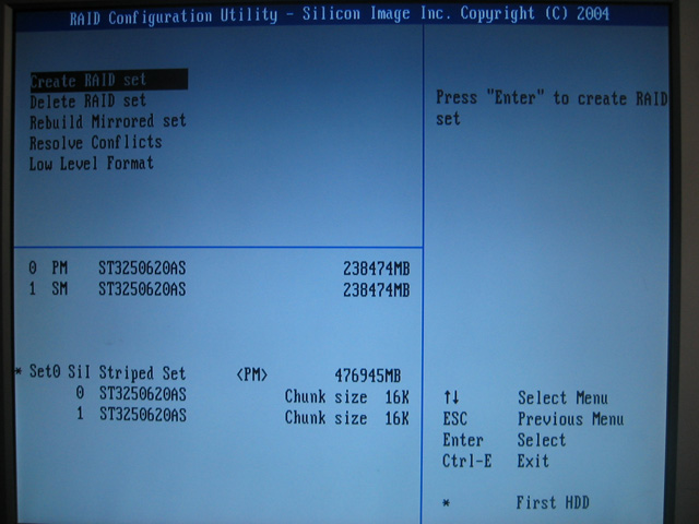
Re-create the RAID 0 array with the correct settings
The RAID controller configuration is usually accessible after a successful POST via a keyboard shortcut (such as CTRL+S and/or F4). With the array broken, no RAID set information will be displayed (only the individual disk details). Re-create the RAID 0 set (striped array) using the correct disk ordering and stripe size determined in the previous steps. It is crucial to note this will wipe track 0 on all physical disks! Once the striped set has been recreated, it will appear below the description of the physical disk. For example:
Restore the MBR and partition information, therefore restoring the file system
As the MBR and partition information both resided in track 0, which was wiped when recreated the striped set, we need to first manually restore the partition information and then automatically recover the MBR. The references to sectors in this section only deal with logical sectors as we are now dealing with sectors on the RAID 0 disk.
The NTFS partition information can be copied back to sector 63 either by restoring it from a backup on a floppy disk or by copying it from a replica found later in the NTFS partition (as shown in the previous section). To confirm that the data is valid, use a human-readable converter to check that the ‘Big total sectors’ value is correct based on the calculations described previously. Other values, such as the NTFS signature, magic bytes, etc, should always be correct.
Recovery of the MBR can be done in many ways. To approach this manually, one could use an MBR editor to create an empty MBR and insert a single entry that describes the NTFS partition with its sector boundaries. Another option could to restore it from a copy on a floppy disk, and check the entry, editing where necessary. The automatic method, and perhaps the safest, is to use partition/MBR recovery software. It will scan the disk looking for partition information blocks (here it would find the NTFS one) to deduce the entries the MBR should contain. Once it has found valid partitions, it will re-create the entire contents of sector 0 and insert the correct entry to describe the NTFS partition. This whole process can usually be achieved simply by following a wizard in modern programs.
Once the MBR and partition information have been restored, the process is complete. You can now restart the computer and pray to your deity of choice.
Thank you for reading this guide! I hope it was helpful. If you have a spare moment, drop me an email telling me of your experience or if you have any comments regarding this guide.
Appendix
The following lists some examples of programs that could be useful in the recovery of disk data:
- Acronis Disk Director Suite (version 9.0)
http://www.acronis.com/ - Paragon Partition Manager Server Edition (version 7.00.000.1274)
http://www.paragon-software.com/ - MBRtool (version 2.2.100)
http://DiyDataRecovey.nl/ - PTDD Partition Table Doctor (version 3.0)
[Doesn’t like corrupt MBRs]
http://www.ptdd.com/ - Ranish Partition Manager (version 2.44 beta) by Muthu
http://www.ranish.com/part